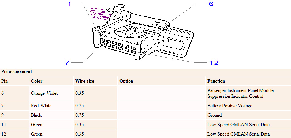
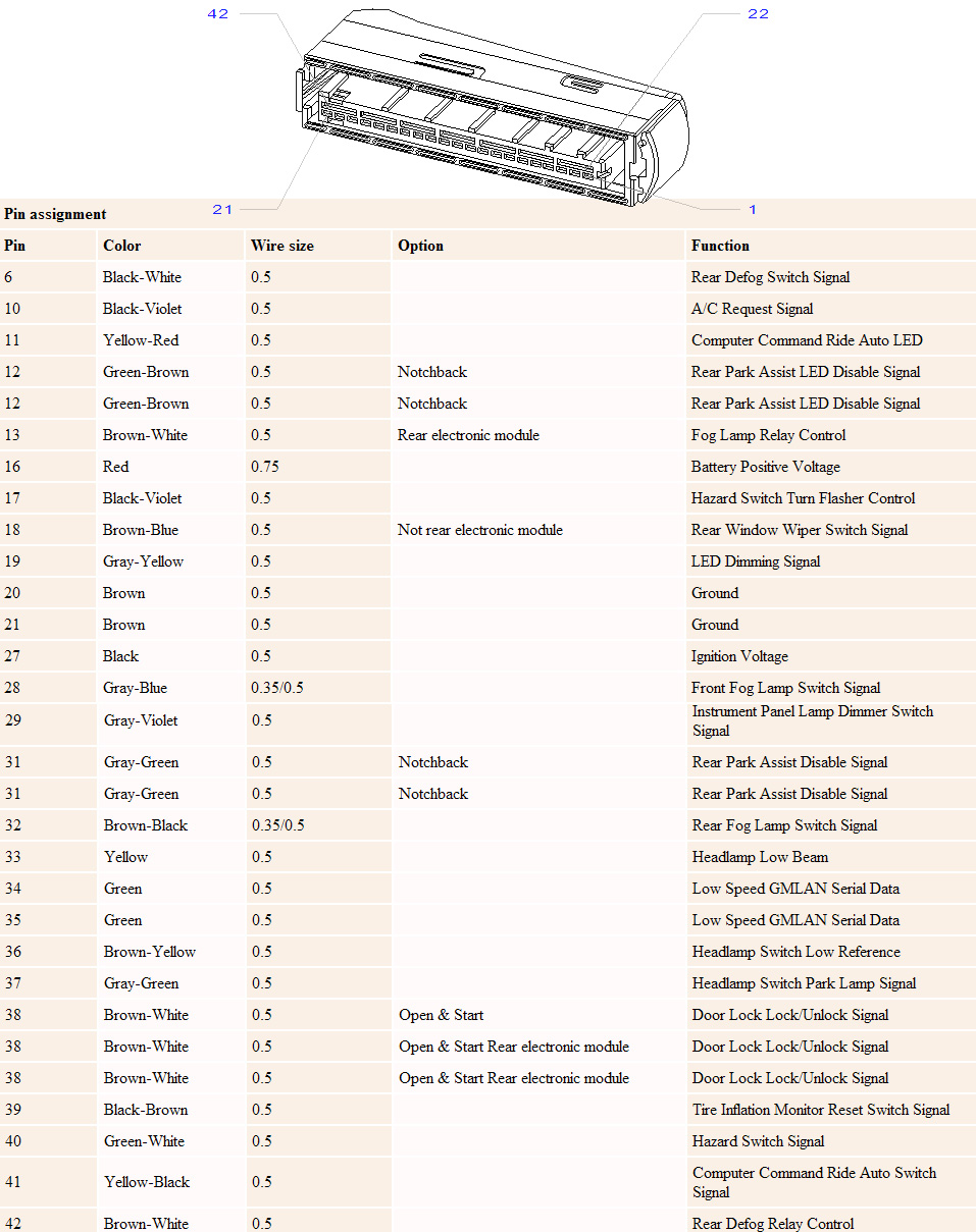
If you are reading this I suppose you are already familiar with GMLAN. In short, GMLAN is a communication protocol based on CAN-BUS to send data between different Electronic Control Units (ECUs) in the car like BCM (Body Control Module), IPC (Instrument Panel Cluster), EHU (Entertainment Head Unit) and so on. GMLAN is a single-wire CANBUS protocol (SWCAN) with 33.3kbps baudrate.
The only thing I wanted was to sniff steering wheel radio commands and send them to control my CarPC, but this turned out very interesting for me to think of other possibilities and ways to make my car smarter.
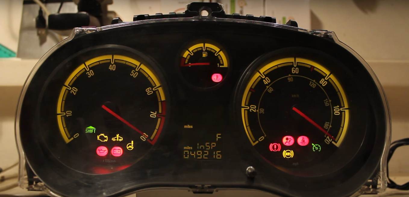
On previous posts you can see that I have an Opel/Vauxhall Corsa D which is an GM (General Motors) car. I have a spare instrument panel cluster (IPC) I bought months ago just laying around, doing nothing. I never installed it in my car as it is incompatible and needs programming with an expensive programmer which I don’t have. So, I wanted to try sniffing the GMLAN and find out the commands to start-up and control the instrument panel cluster.
For this project, I’m using Arduino Nano with MCP2515 controller and TJA1040 transceiver module. If you have 8MHz crystal oscillator on the MCP2515 board I would suggest changing it to 16MHz. Below is the wiring schematic:
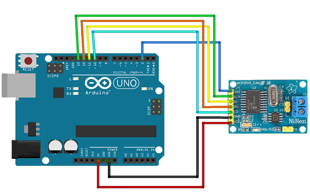
Connect CANH to GMLAN wire and CANL to GND. Interconnect grounds from Arduino, to MCP2515 board and your car or module you want to sniff messages from.
Next step is loading MCP_CAN_lib library in Arduino IDE. Before trying to send messages, I would suggest first trying to read. In the library examples load the file named CAN_receive.
For sniffing GMLAN Low Speed CANBUS, adjust baudrate to CAN_33K3BPS.
Upload the code, turn on your car or module and start the Serial Console from Arduino IDE. You can also use PuTTY or Realterm if you are using Windows, or if you are using Linux, you can just type screen /dev/ttyACM0 or screen /dev/ttyUSB0.
I found the commands for starting up the IPC, rev and speed gauges, turn signals and chime.
Here are the CANIDs I discovered and used on this project:
CANID | DATA | Description |
632 | 0x00, 0x48, 0x50, 0x00, 0x00, 0x00, 0x00, 0x00 | Wake GMLAN before transmitting data. |
170 | 0x74, 0xA1, 0x3B | Turn on IPC (Instrument Panel Cluster) |
170 | 0x60, 0x00, 0x00 | Turn off IPC (Instrument Panel Cluster) |
146 | 0x15, 0x00, 0x00, 0x00, 0x00, 0x00, 0x00, 0x0C | Turn on Cruise Control symbol |
146 | 0x00, 0x00, 0x00, 0x00, 0x00, 0x00, 0x00, 0x00 | Turn off Cruise Control symbol |
260 | 0x7F, 0x32, 0x80 | Turn on Hazard lights |
260 | 0x20, 0x32, 0x80 | Turn on Left turn signal |
260 | 0x30, 0x32, 0x80 | Turn on Right turn signal |
260 | 0x00, 0x00, 0x00 | Turn off Hazard lights/Turn signals |
350 | 0x06, 0x01, 0x92, 0x20 | Turn on lights symbol |
281 | 0x60, 0x05, 0x1E, 0x01, 0x33 | Chime (experiment with values for different sound) |
108 | 0x00, i, 0x00, 0x00,i, 0x00, 0x00, 0x1E | Speed and RPM full sweep |
I used CAN_send example loaded with the appropriate commands and sent them to the IPC.
See it in action:
Wow! Awesome project!
In fact, I’m currently trying to read the steering wheel controls as well, but I don’t quite have the experience with CAN.
Would you mind sharing the Arduino code for the CAN sniffing, or even better the CAN codes for reading the steering wheel controls (if you found them already, if not, the codes for the IPC would also be interesting)
Yes, I will add the code on this post. Thanks for your comment! π
Awesome project, cant wait for it.
I want to do the same with my astra h cd30, so i will be here waiting xD
keep up the good work!
Thank you for your comment! I’m currently busy with planning and rebuilding my workshop, when I finish I will continue this project.
Please dont give up =)
Yes, don’t give up!) I am from Ukraine, and couple week I try to connect to my Vectra C 2006… π Today I change crystal to 16 MHz if find in my city and try again… Could I Ask you to send my soft part, and I am give some log files and other info for it? Thanks in advance!
Do you still have the radio working? Is it possible to keep using it?
WOW, i have been playing with LOW Speed GM-LAN for the past few days…
i have my arduino and MCP2515 all set up… i am trying to do something very similar to you actually…
i have a instrument gauge that is from a slightly newer model car than what i have and I’m trying to send the appropriate can message to control the gauge… only problem is, using the same library you are using i cannot get a send command to work. i have the can initialised and running at 33.3kbps…
the only thing is i am not using the TJA1040 transceiver. is it a must?
Are you using MCP2515 module for Arduino? If you do, check the oscillator/crystal, and if it is 8MHz, change it to 16MHz. That board already has the transciever TJA1040 built-in. Connect instrument cluster ground to CANL and Arduino GND, and GMLAN Wire to CANH.
yeah I’m using the MCP2515 module… i have ordered the 16MHz crystal… hopefully that fixes my problem. cheers for the reply.
I’ve been searching for something similar and I found this:
https://docs.google.com/spreadsheets/d/1qEwOXSr3bWoc2VUhpuIam236OOZxPc2hxpLUsV0xkn0/edit#gid=1
I think it might be a full list of possible canbus input for our GMLAN. Hope it helps.
I succed in reading the radio steering wheel control; many interfaces take tha canbus signal from the green wire behind the TID, which is connected to the 33.3kpbs canbus line. Unfortunately I couldn’t read anything from there so I took the signal from the CAN H and CAN L pins behind the radio on the quadlock connector. These are connected to the 95kpbs line so you need a different library from the MCP CAN which is not compatible with this speed. I advice you to use the Seed studio Canbus library instead. After many imprecation and a lot of coffee, I found that steering wheel control are associated with the ArbID 206 (hex coded). Here the list of the various commands I found:
ID Data (HEX) Function
206 (518) 8 93 1 Volume UP
206 (518) 8 93 FF Volume DOWN
206 (518) 1 92 0 Track UP
206 (518) 1 91 0 Track DOWN
206 (518) 8 83 FF Select UP
206 (518) 8 83 1 Select DOWN
206 (518) 1 84 0 Select OK
206 (518) 1 81 0
206 (518) 1 82 0 Close call
Hope it could help.
Awesome! Thank you. Do you have an Opel Corsa D as well?
Yes I have a Corsa D restyling and I’m trying to setup an infotainment system using the Odroid platform, the same you did with raspberry. I will control Android through some of the steering wheel controls. Anyway, could you share the codes for controlling the RPM and speedometer on the IPC?
Thanks a lot
Great! Here is the code to start the IPC – ID 170, HEX 74, A1, 3B. Here is the code to make full speed and RPM sweep – ID 108 HEX 00, FF, 00, 00,FF, 00, 00, 1E.
Greetings!
Many thanks!!!!
Hi. i just bought same IPC for testing. But I can not find pinout of 12 pin IPC connector. Would you please let me know? Thanks in advance.
Sorry for the late reply, I have been very busy. If you still haven’t found it here is the pinout –
http://blog.dimitarmk.com/wp-content/uploads/2017/08/CorsaDIPCPinout.jpg
Hi, I have a cluster from an AH Astra (Australian version of the Astra H/mk5). Could you please post the pinout for your cluster and the full wiring diagram for your setup. I assume it’s the same.
As I can see from the pinout, Astra H is also using GMLAN for some portions of the IPC but lot of stuff is directly wired from the switches and relays. Here is the pinout for the Astra H/MK5 – http://blog.dimitarmk.com/wp-content/uploads/2017/08/AstraHIPCPinout.jpg
I have posted the Corsa D IPC pinout in the comment above, so you can compare them, there is a lot of difference.
Awesome!
I tried to βcloneβ everything but have the same problems like Ray: I can read with no problems, but writing always returns a MCP timeout (7)
Any advise?
Can you provide me the script you are using for sending commands? If you are using MCP2515 module with TJA1040/50 transciever you probably have 8MHz oscillator. Try configuring the library for 8MHz, or change the oscillator to 16MHz.
can you write all can id in your project